

In the previous posts, I focused on analyzing Scratch projects. There are no hardware components. Since now we are preparing for LEGO MINDSTORMS EV3 courses, I will introduce a robot model made of EV3 and discuss some issues met in the designing process.
Let me show the result first.
What is the Task?
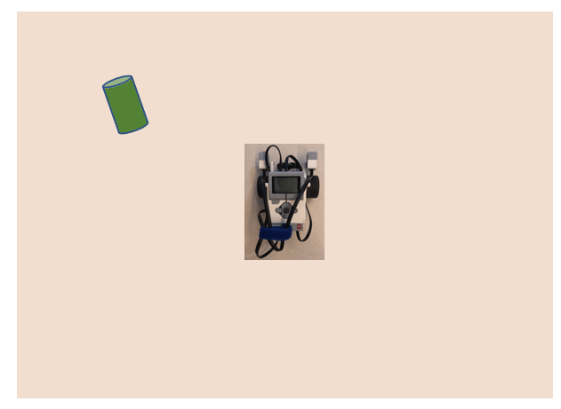
The task is simple. Put a small object close to the robot at any angle and make the robot find it. After that, the robot should carry the object back to the starting position. The robot should face the same direction as that at the beginning.
Easy, right? However, when I try to combine the hardware together with software to make the system rock, lots of problems happen. Sometimes, the ultrasonic sensor cannot identify the target object correctly. Sometimes, it identifies, but just not faces it straight. Sometimes, the front attachment cannot catch the target successfully.
Robot Task Planning
When we design a game in Scratch, the first and foremost step is to plan the program: plan the sprites (characters), their actions, interaction and win/lose condition. The planning process applies to robot design as well. We need to decompose the tasks into small steps or sub-tasks. Then we think about the mechanical structure and the arrangement of sensors and motors. We also think about how to use programming blocks to control those hardwares.
- Decompose the tasks
- Planning the mechanical structure and layout of sensors, motors.
- Planning how to control effectively using program.
The above steps, especially step 2 and step 3 might iterate several times. That is where EV3 robot design is different from Scratch programming. The latter is a pure software program. All of the functions are realized by code. While the former is an integrated system and it could not depend solely on mechanical structure or program. We have to make the mechanical design and program work seamlessly.
Task Decomposition
Based on the previous task description, I separate the task into a detailed task list.

Mechanical Design
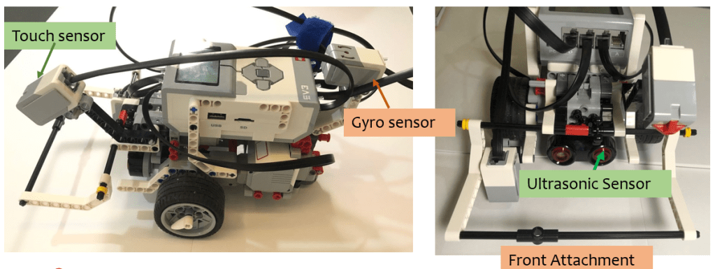
Based on the task list, we could consider what sensor(s) and motor(s) should be used, how the front attachment should look like and how to arrange the motors and sensors so they will not interfere with each other.
There are lots of choices for your design. Draw your design on the draft paper and brainstorm with your teammates. You could design a very basic vehicle with a simple bar-like attachment, or you could upgrade it into a fancier model with panels on both sides to catch the target more easily.
Please keep in mind that not all the fancy models do a job effectively. The position of sensors and motors will also affect the final performance.
Sample model 1 – model with a simple bar attachment.
Sample model 2 – model with a fancier attachment.

Planning Your Program
At The Coding Fun, as usual, we will always pay much attention to the program. There is no exception in this post. So after designing the initial version of mechanic structure, we could design the initial version of program. Please note here I mention the “initial version” twice. As I say at the beginning, the hardware and software form an integrated system, therefore, both might make adjustment repeatedly in order to cooperate with each other and make the system run smoothly.
The task list mentioned above is an important guide in designing the programming blocks.
Programming Segment 1 – lift up the attachment
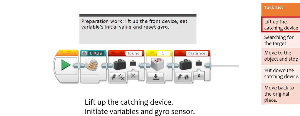
At the beginning of the program, I use a “Lift Up” block to lift up the front attachment. The code in this self-designed block is simple and easy to understand. It drives the medium motor to turn until touch sensor is pressed down by the bar. I also initiate variables “found” and “distance”, and reset gyro sensor.
Program Segment 2 – Searching for the target
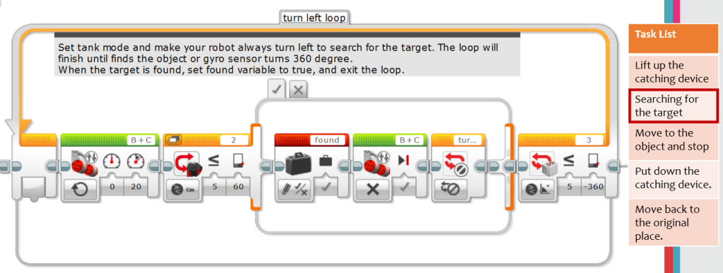
When searching for the target, the program sets left motor power to 0 and right motor power to 20. In this way, the robot always turns left. If the ultrasonic sensor identifies any object within a distance of 60 centimeters (you can change this range), the program will set “found” variable to True, stop the motors and end the loop. However, if the robot has turned 1 round but not yet finds any target, the loop also finishes but the variable “found” is kept as False.
Program Segment 3 – Move to the target and stop

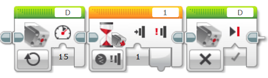
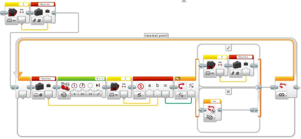
The ultrasonic sensor uses ultrasonic to detect the distance of the target. When the robot turns left continuously and finds the target, since the sensor’s searching area is a fan shape, the target is not right ahead of the robot, but to the left. Here I uses a self-designed block called “minor adjustment” to adjust the robot and make it face straight toward the target.
The block is shown as below. When the ultrasonic sensor identifies the object, it stores the distance value in a variable called “Nearest_distance”, then turn the motor to the left a little bit (here, I make right motor turn 15 degrees) and record the current ultrasonic value. If this value is smaller than the recorded value of “Nearest_distance”, the program will update the variable “Nearest_distance” to the smaller value and then repeat the loop. Otherwise, the block stops the loop and declares the end the adjustment.
Program Segment 4 – Put down the attachment and then return back when “found” value is True

In this segment, the robot will move to the target object first. Since the program has adjusted its direction in “Minor Adjustment” block and assumes that the robot is facing the target straight, it sets both motors to the same power of 30 and goes straight toward the target. The travelling distance is calculated by using the formula (distance variable – 3) / 19. “-3” is used to compensate the distance difference between ultrasonic sensor’s position and motor’s position. “19” is the perimeter of the wheels. This formula changes the distance into the rotation count of the wheels and acts as an input to the “Move Tank” block.
Then, the medium motor turns a certain degree to put down the front attachment.
After that, the program uses “Move Tank” block to set both motor’s power value to negative and turns the same rotation count. It ensures that the robot retrieves back to the starting position, but at this moment, it is still facing the direction of the target. In order to make it face in the initial direction, the program continues to make the robot turn left until Gyro sensor’s value is set to 0 (at the beginning of the program, Gyro sensor is reset so the initial direction’s gyro value is 0).
Program Segment 4 – stop the motor and alert when “found” variable is False.
For this segment, the program checks the value of variable “found” first. If the target is found, the robot will move to the target. Since the program assume that the robot has made adjustment and faced the target straight, it will use tank mode and set same power to both left and right motors. How long
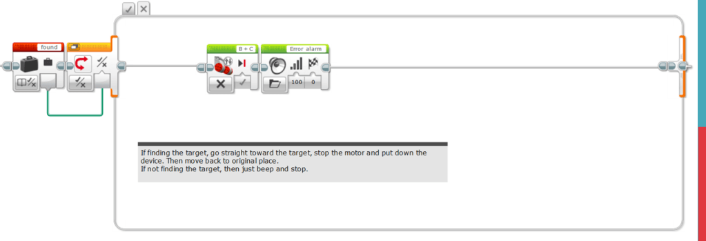
When “found” variable is False, just simply stop the motors and give out an alarm sound. That is all.
Conclusion
There are several ways to improve the model. One way is to improve the mechanical design, for example, design a more effective front attachment, instead of the simple bar system. Or you can install sensors at different position to identify the target more accurately.
Another way is to utilize software programs to better control your sensors and motors. When measurement errors occur due to the precision limitation of motors or sensors, we can use program to compensate those errors and generate a more robust result.
In a nutshell, robot is an integrated system of mechanical and electrical engineering. Its electrical part further consists of hardware components and software program. Therefore, its design process is different from pure software program. On one side, mechanical structure is the basis. If your model installs sensors and motors at various position, or uses different sensors to implement function, the program will definitely differ. On the other side, the design of the program will also influence the performance of the robot. Under certain conditions, program could compensate the precision errors of the sensors.
So enjoy the design and have fun! See you then!
