
In the previous posts, I introduced two models: Santa Claus model and Spinner model. Both of them have some structures in common. They both use offset shaft structure to design legs to mimic the running gesture of a creature. In this post, I will introduce another interesting model: forklift truck.
the original link of this model can be found here:
https://www.youtube.com/watch?v=3Vbf56Wm-wA
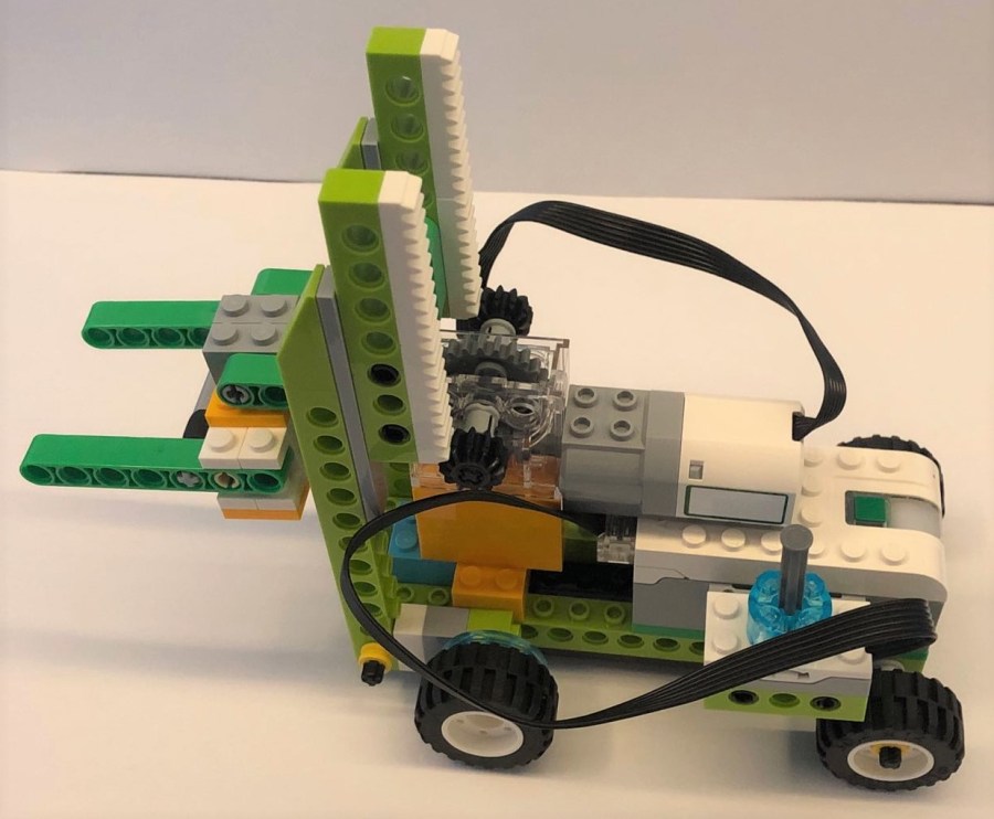
In this project, the author controls the movement of rack by using tilt sensor. It uses gear box to change the rotation direction of the motor, and then uses rack and pinion structure to convert the rotation movement into linear movement. Watch the above video to check its effect!
What Can We Learn from its Mechanical Design?
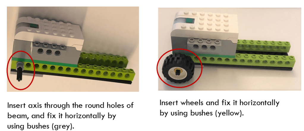
Point 1: use beam to provide support to axis.
In this forklift model, wheels are not linked to the motor at first. The axis passes through the round holes of green beams and rotates freely. If you have seen the above video to the end, you will notice that one front wheel uses belt drive to connect to the gear wheel output, so that the forklift model can move forward and backward when the fork is lifting or putting down.
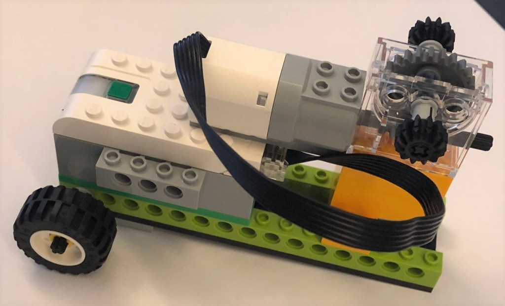
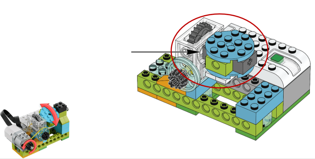
Point 2: gear box.
Remember that when using gear box, the worm is always the input gear, and the regular gear is the output gear. It cannot be reversed due to the self-locking mechanism.
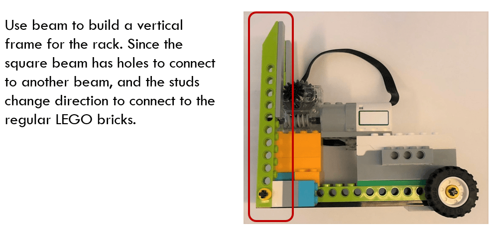
Point 3: use beam to change the connection direction
The square beam has the regular studs on the top and holes side ways. Connect the holes of two beams using pegs, and the beam then changes the direction and its studs can connect to the regular LEGO bricks as shown below.
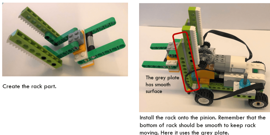
Point 4: Create the rack structure.
In order to make rack move, the bottom of the rack should keep smooth to move around. In this model, it uses grey plate to touch the bottom of the rack structure. Since the grey plate has not stubs so is smooth enough to work together with the rack.
Find the Similar Structure from Guided Projects
The above mentioned structures are already used in the guided projects, but the author combines and implements them flexibly. That is why I always emphasize the importance of guided projects. We can extend a structure to other scenarios or make several structures work together. In the below section, I will explain a bit more about the two mechanical structures and their usage.
Rack and Pinion Structure
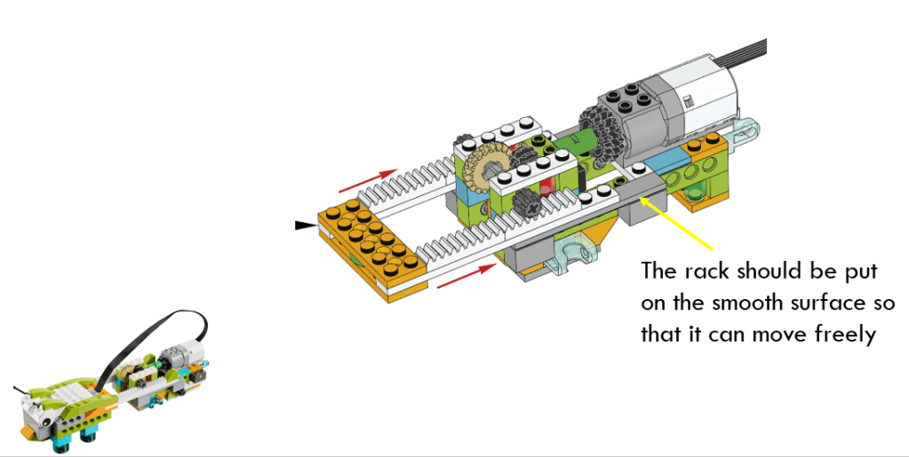
A rack and pinion is a type of linear actuator that converts rotational motion into linear motion. A circular gear called “the pinion” engages teeth on a linear “gear” bar called “the rack”; rotational motion of the pinion converts into the linear motion of the rack.
We have seen the similar rack and pinion structure in the guide project – pushing device, or caterpillar project, as shown below. It uses bevel gear to change direction of motor output and then the gears are connected to rack. In the forklift truck model, it uses the gear box and then connects output gear to rack structure.
Gear Box
Gear box consists of a worm and a regular gear. When the worm turns, the groves push the teeth on the regular gear and cause the regular gear to turn.
Please notice that the WORM is always the input gear and cannot become an output gear.

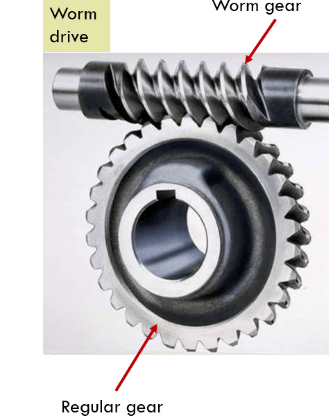
It seems that both bevel gear and gear box convert rotation from one direction to another direction, so what is the difference? There are some special characteristics of worm gear.
- worm drives can be used for extreme gear ratios. In our project, the regular gear has 24 teeth. The worm has to spin 24 times for the regular gear to rotate once.
- Worm drive is an effectively one-way valves for mechanical motion. The worm can cause the regular gear to spin, but the regular gear cannot cause the worm to spin. This can be used to cause braking effect.
In the above guided object – revolving, it uses belt drive to transfer the rotation of motor parallel to the rotation of worm, and then convert into the rotation of output gear through gear box.
Use LEGO Code Editor to Program Your Device!
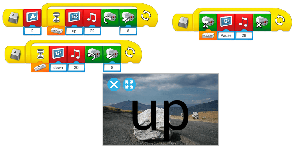
The program uses “Start on Press Key” block to build three parallel running code strings. Tilt sensor will monitor its position all the time (because it is put in a loop) and decide the motor running direction, the music to play and the message to show up.
There are other auxiliary parts showing in the video, such as the belt drive which connects one front wheel with the output gear, so that the truck will move forward when its fork is putting down, or move backward when fork is lifting.
I tried to use this structure but it seemed not so steady because the elastic band will tip over the gear box. You could think about ways to make the structure more solid, such as adding elastic band on both sides, or putting extra blocks around gear boxes to fix it. Anyway, enjoy your design and coding!
