

No matter your participate in World Robot Olympiad, LEGO First League competition or build just for fun, one typical task is to make your robot catch some objects and carry them to the destination. One solution for this task is to design a grip to pick up the target. Now let me introduce three methods of designing a grip and then compare their advantages and disadvantages.
All of those grips could be attached to the tutorial drive base shown in the above diagram. You could find the step-by-step instruction of tutorial drive base in LEGO MindStorms software.
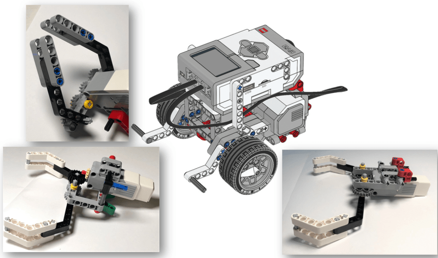
Method 1 – Using Gear Train
The first solution puts medium motor in front of the robot and perpendicular to the ground. The axis connecting to the medium motor drives a gear (input gear) and it then drives another three gears. Each output is connected to a grip. When the motor drives, the two grips will spin in opposite direction to mimic the open and close action of grips.


This grip structure is mounted to the robot body by inserting two friction pegs (black color) into the pin holes of a frame. In a nutshell, the structure is concise and easy to understand.
Method 2 – Use Bevel Gear
The second solution uses bevel gear. Part of the medium motor is inserted into the lower body of the robot, and the other part is extended to the front of the model. When arranged in this way, the structure uses a bevel gear to change the direction of the drive. It then uses a 5*7 frame to fix the gears to the medium motor and to the robot body.

Another difference between solution 1 and 2 is that the former uses gear train (four gears aligned in a line), while the latter uses just two gears (gray color). They are similar but gear train transfers the drive more smoothly.

Attaching this structure to the robot model is a bit complicated. It uses two 3-module beams (green color) and connector pegs (red color) to fix it to the robot. It is a bit time-consuming to amount and dismount it so it is not recommended for scenarios requiring fast replacement.

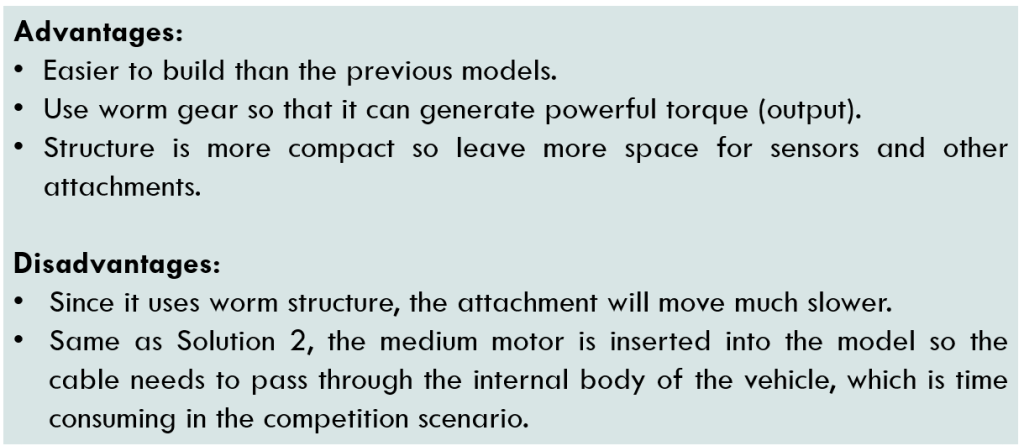
Solution 3 – Use Worm Gear
This solution uses worm gear to drive two regular gears as output. The gears are spinning in the opposite direction to drive the two grips open or close.
The medium motor’s layout is similar to that in solution 2, that is, half of it is put inside the model and the other half is extended outside. The structure is concise and its connection to the robot body is succinct, too.
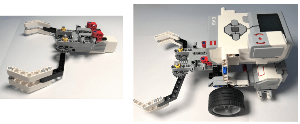

As we know, the worm gear will reduce the rotation speed of the output dramatically, meanwhile, it increases the output torque. In this model, the regular gear has 24 teeth. The worm has to spin 24 times for the regular gear to spin once.
Check the following video to see the response speed of the grip. It is slower, but the grips are much stronger and stable.
Those are all of the three designs. Which design is your favorite? Anyway, enjoy the creation and have fun!
Note: All the analysis articles are copyright products of http://www.thecodingfun.com. Anyone re-posting them should credit author and original source. Anyone using them for commercial purposes or translating them into other languages should notify TheCodingFun and get confirmation first. All Rights Reserved.

This is a theme provided by WordPress. The name is Colinear.
LikeLike
Hallo Your method of explaining all in this article is really fastidious, every one be capable of simply know it, thank u
LikeLike