
In my previous post, I introduced a way to design a mission for LEGO Spike Prime, so that even without the competition map of FLL or WRO, you could still sharpen your programming skills of LEGO robot vehicles at home. In today’s post, I would like to continue this method but introduce a different map and mission.
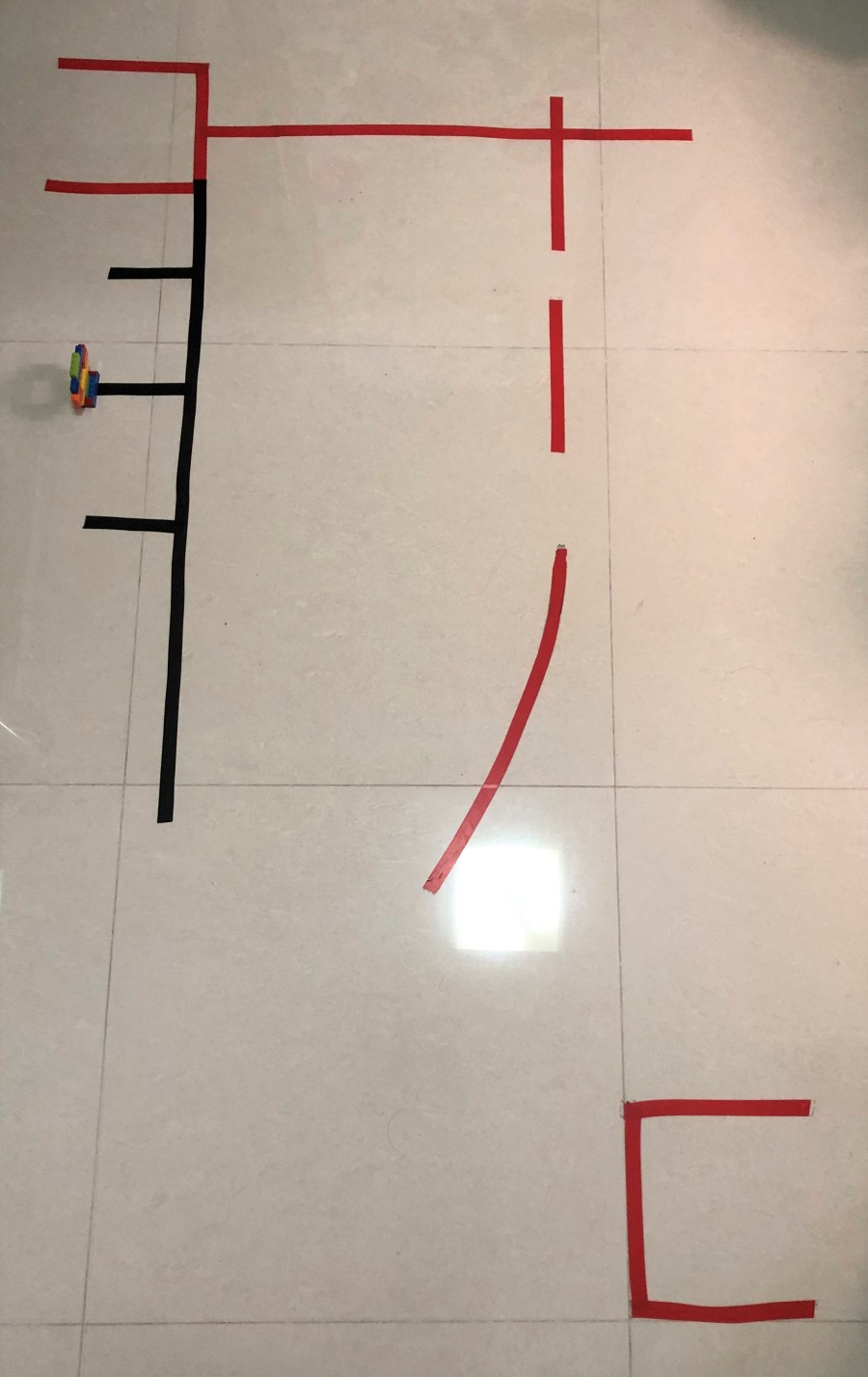
The setting in this challenge is different. First of all, the route is made of black tape, so that colour sensor could differentiate the reflective light of the black route from the white gound. The program therefore could use proportional line follower method. Second, the mission is different from previous ones. The object is put randomly among three possible positions. The program needs to use ultrasonic sensor to recognize the object first and do the corresponding actions.
The connection to each port is shown below. If you are using the same program for your model, you might need to adjust port connection.

As usual, I will explain the program in this post, and introduce the mechanical structure in the next post.
“when program starts” Code Segment
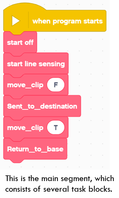
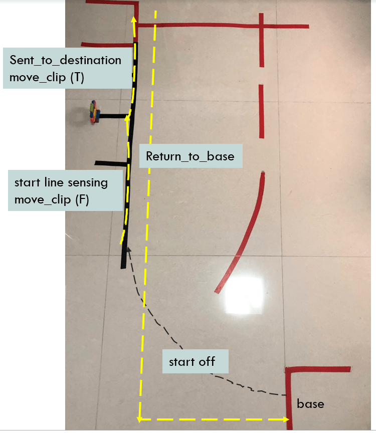
This code segment wraps all the main activities in this project. The vehicle starts off from the base by turning right a certain angle. It then drives forward until touching the black line, which is implented in “start off” segment. After that, it moves forward along the black line until the ultrasonic sensor identifies the object. This is implemented in “start line sensing” code segment. The program calls “move_clip” to put down side attachment. After that, it still follows the black line and transfers the object to the destination by calling “Sent_to_destination” block. The program calls “move_clip” again to loosen the object. The last step in the whole mission is “Return_to_base”. Those activities are illustrated in the below image.
In the following sections, let me analyze the blocks one by one to understand how the program controls the vehicle.
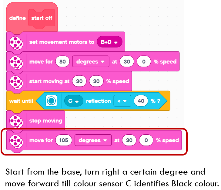
“start off” Code Segment
In this block, the program first moves for 80 degrees at 30, 0 % speed. The purpose is to make the vehicle turn right a certain degree. It then starts moving straight at 30, 30 % speed until the colour sensor connecting to port C identifes the black color (reflective light smaller than 40%).
After that, the vehicle moves for 105 degrees at 30, 0 % speed. The effect is that it turns right a certain degree to keep aligned with the direction of the Black route. It is now going to enter the next step.
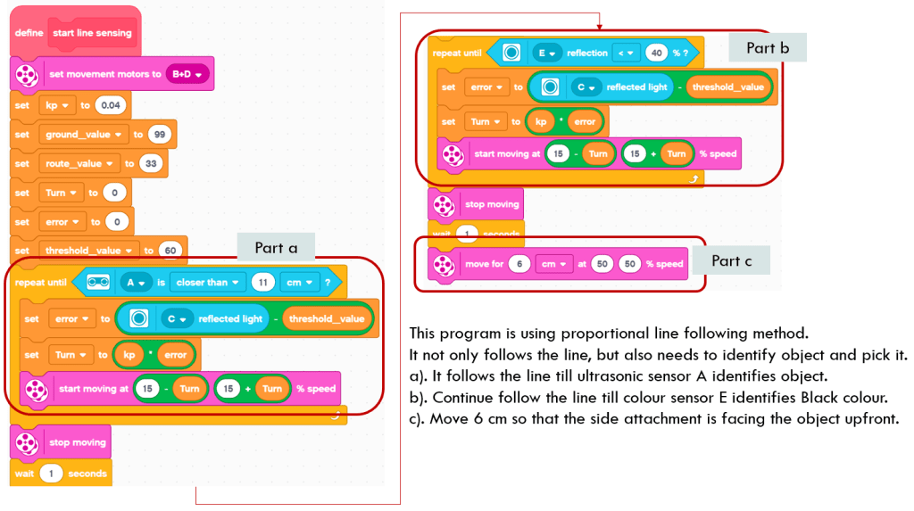
“start line sensing” Code Segment
This block is the core of the whole mission. It consists of three steps. In Part a, it specifies the parameters of proportional line follower method and moves until the ultrasonic sensor identifies the object. The nexet step of Part b, the program continues running along the black line, until the colour sensor connecting to Port E identifes the black line (reflection light < 40), which means the vehicle has reached the intersection where the object is located. It then moves forward for another 6 cm so that the side attatchment could face the object right in front.
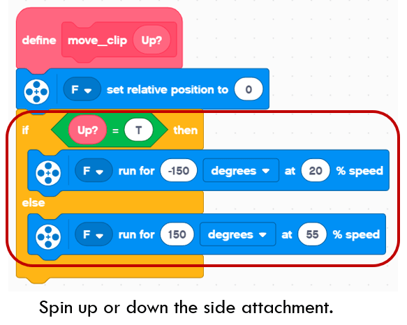
“move_clip” Code Segment
This block is simple. It just drives the medium motor connecting to Port F to run a certain degree. When Up? variable is T, it runs -150 degrees to lift up the clip. When Up? variable is F, it runs 150 degrees to put down the clip to grip the object.
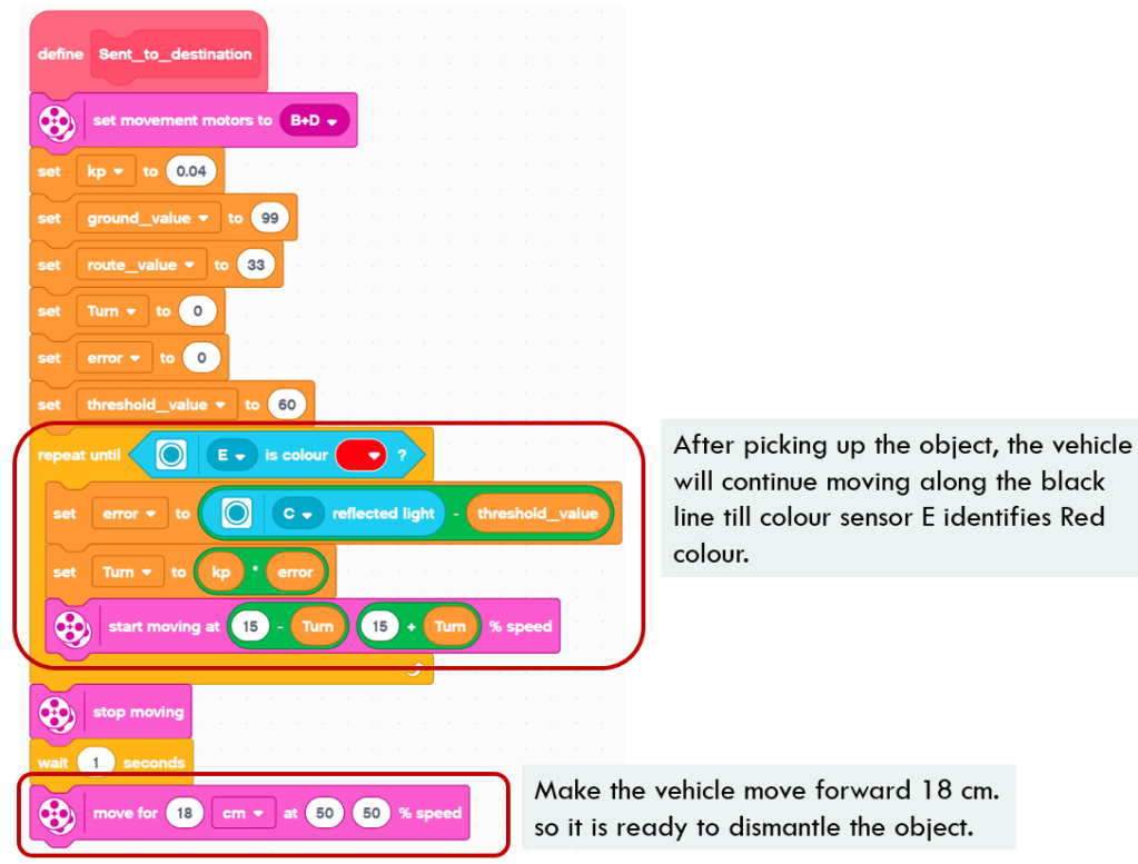
“Sent_to_destination” Code Segment
Once getting the object, the program will make the vehicle continue following the Black line until colour sensor connecting to Port E identifies the Red colour. It means the vehicle has reached the object destination. It will move forward 18 cm to reach the point where it could put down the object.
“Return_to_base” Code Segment
You might think the mission is done after sending object to destination, but the answer is no. Another challenging task is for the vehicle to return to its base. Like what WRO competition requires, the whole vehicle body should be within the boundary of the base.
First, the vehicle turns 180 degrees (when yaw angle > 178). At this moment, the vehicle should stay a little bit behind the Red line as shown in the above video. The next step for it is to move foward until both colour sensors identify Red colour. This step is necessary since we could not ensure an accurate position and direction of the vehicle without referring to some marks on the map. When those errors accumulate, the vehicle will deviate much from the target position and direction.

When both colour sensors identify red colour, it means the vehicle is standing at the right place. The program makes the vehicle go straight 134 cm, and then turns left. The vehicle is now facing the base upfront. It will move forward until both colour sensors identify the red edge of the base.
The last steps for the vehicle are to move into the base by 14 cm, and turn around to declare the accomplishment of the mission.

That is all for the analysis of the controlling program. Feel easy to do? Try it at your home now. Enjoy the coding and have fun!
Note: All the analysis articles are copyright products of http://www.thecodingfun.com. Anyone re-posting them should credit author and original source. Anyone using them for commercial purposes or translating them into other languages should notify TheCodingFun and get confirmation first. All Rights Reserved.

Pingback: Play LEGO Spike Prime at Home – Another Mission for Your Robot Vehicle – Part 2 – The Coding Fun