

In the previous post, I introduced how to design a mission for the Lego Spike Prime vehicle at home and explained a sample program in detail. In this post, I would like to introduce mechaical structure of the model.
Top View
The top view of the model is shown below. It has a front attachment which is operated by two medium motors. One of them is responsible for lifting and putting down the attachment. The other motor is responsible for opening and closing the clip.
The smart hub is put on the top of the model. It is arranged near to the rear part of the model. This is to offset the influence of front attachment on the tilting of gravity center and keep the model balanced.
The red beam in the middle of the model is used to organize the data lines.

Bottom View
In the bottom view, you could see the two colour sensors clearly. They are mounted on both sides of the model. Besides the two big wheels to drive the vehicle, the third wheel is a passive one with the purpose of keeping the model balanced.

Internal Structure
Remove the smart hub on the top, we could see the internal structure of the model. Generally, the chassis design is pretty concise. It uses a 7*11 frame panel to mount the two big motors and one medium motor, all with black friction pregs. There are still ample place in the middle of the body, allowing data lines to pass through or being stored there.

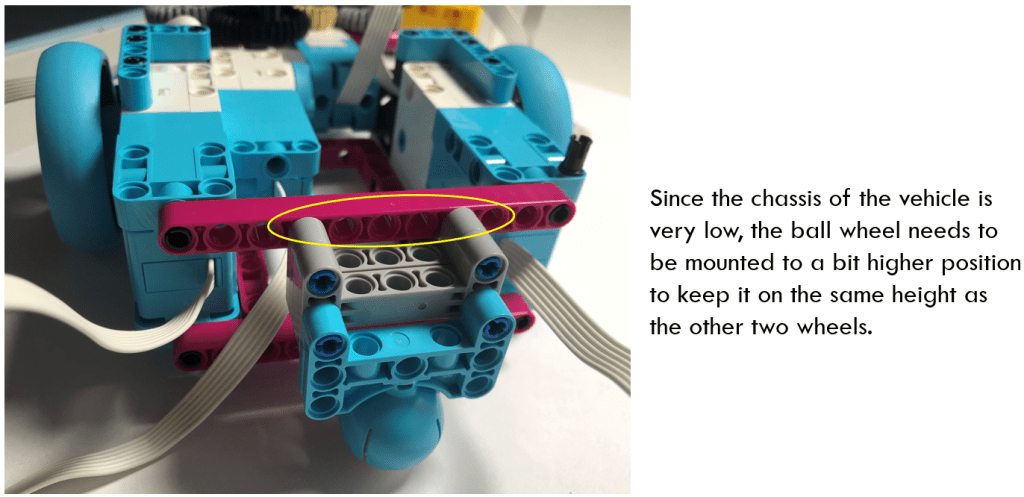
Rear Part
The rear part is left for installing the ball wheel. In Lego Spike Prime, ball wheel is much easier to be mounted than in LEGO MindStorms EV3. Since the chassis of the vehicle is very low, the ball wheel needs to be mounted at a bit higher position to keep the three wheels on the same height. It is mounted to the red beam through two stacked I-beam (gray colour).
Front Attachment
The front attachment consists of 4 gears to form a gear train. The yellow 20-teeth gear is an input gear, which connects to the medium motor (on Port B). It transfers the spinning energy into the other gears. The gray gears on both sides spin in opposite direction. Since they are of the same size, they spin in the same speed, making the clip open and close symmetrically.
The red biscuit blocks are used to fix axle of the gears. Please note the black 36-teeth gear is not installed at a straight line as the other gears do due to the space constraint. However, if we replace the big black gear with other gear, say the 20-teeth gear, the axle position falls half stud offset from the standard pin hole distance, making it difficult to fix the axles. Through positioning black 36-teeth gear a bit offset, this problem is solved, although it is not a perfect solution.

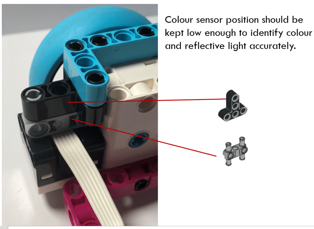
Colour Sensor and Wheel Intallation
The colour sensor is mounted to the big motor through a T-shape beam and a connector beam, as shown below. The bottom of the colour sensors is aligned with the chassis.
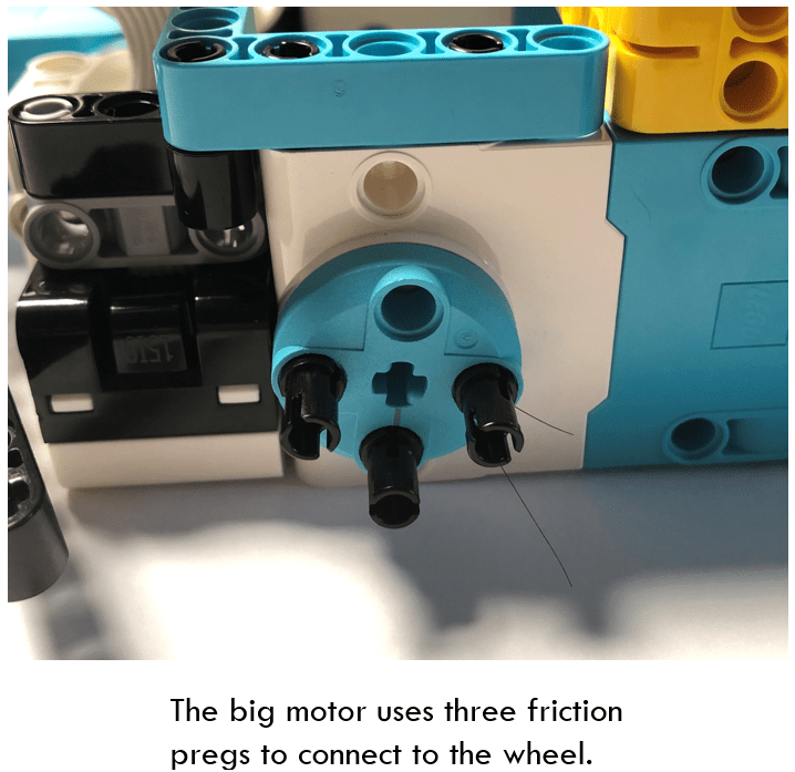
For the two wheels, they are connected to big motors via three black frction pregs.
That is all for the mechanical structure of the model. When we design a robot vehicle for a mission, the first thing is to understand its mission and design its attachment first. After that, we will assemble the attachment to the chassis and add sensors, wheels and smart hub. The layout of those components should consider both the space constraint and the influence on center of gravity.
Try to build a model by yourself and experience the convenience of LEGO Spike Prime. You would like it!
Note: All the analysis articles are copyright products of http://www.thecodingfun.com. Anyone re-posting them should credit author and original source. Anyone using them for commercial purposes or translating them into other languages should notify TheCodingFun and get confirmation first. All Rights Reserved.
