
In previous posts, I have explained how to make the EV3 vehicle follow a line and square up with a line or wall. In this post, I would like to explain another important technique: how to make the EV3 robot recognize stalling status and then adjust itself to end stalling in time.
What is Stalling?
So what is stalling? Stalling is a condition at which a motor stops rotating even when there is sufficient voltage at its terminals. This condition occurs when the torque required by the load is more than the maximum torque that can be generated by the motor. For example, when the motor is overloaded, or the mechanical parts driven by the motor confront some obstacles, the motor has not enough “strength” to sustain the load.
Stall could also happen when battery is low. Both medium and big motors could get stalled. Since the maximum torque of big motor is higher than that of medium motor, stalling might happen more frequently on the medium motor.
What happens when stalling?
When stalled, the motor will continue to provide torque. In another word, the motor is still trying to spin, but fails. If left in a stalled condition too long, it is prone to overheating and possible damage since the current flowing is maximum under these conditions.
Therefore, when we design an EV3 robot, we should consider different stalling possibilities and use program to reduce the occurrence of stalling.
Examples of stalling
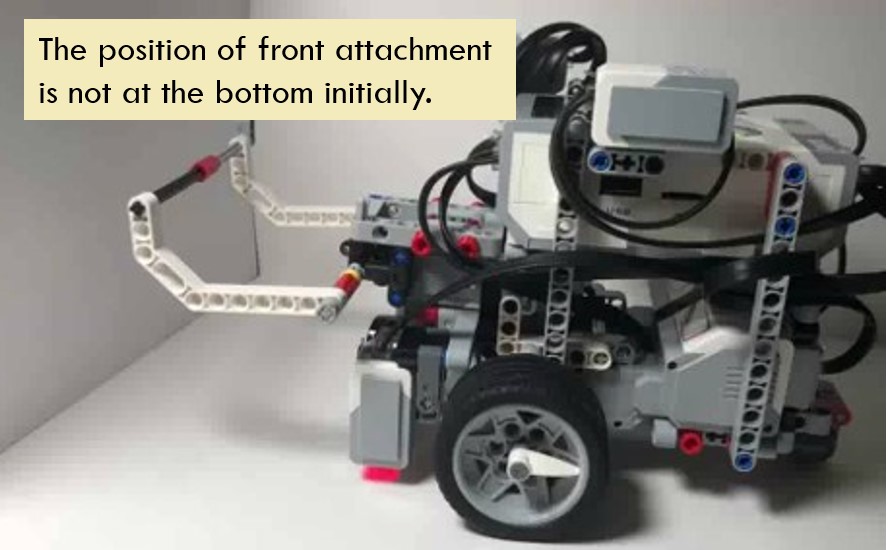
As I mentioned above, stalling may happen when the mechanical parts driven by the motor are blocked by some obstacles. In the below video, the front attachment of the vehicle is driven by a medium motor. When the front attachment spins to the lowest or highest point, it could not spin further since it is blocked by the vehicle body or the ground.
In another example of a puppy model, the legs could swing in a certain range. However, it will be blocked by its body when it tries to swing backward or forward further. The rotation of the head also falls into a certain angle. Beyond this range, the motor will get stalled.

There are several ways to identify and then end stalling status. I will introduce them one by one and then compare their advantages and disadvantages at the end of the post.
Method 1: Estimate running time
This is the simplest method. It estimates the running time of the motor before it reaches the stalling angle. In this way, even if stalling happens, it will not last long and the motor will not get affected too much.
Take the above front attachment as an example. The sample code below turns medium motor anti-clockwise for 2 seconds to reach the highest position, pause 2 seconds, and then turns motor clockwise for 2 seconds to reach the lowest position.
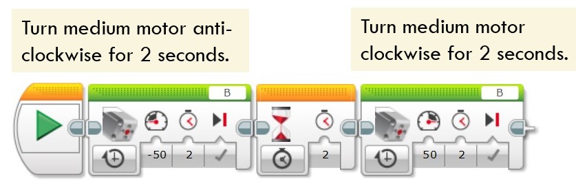
This method is based on rough estimation, so the control is less than accurate. Moreover, if the front attachment is not put at the initial lowest position, but hangs in the middle, the stalling time might be longer.
Method 2: Use Touch Sensor
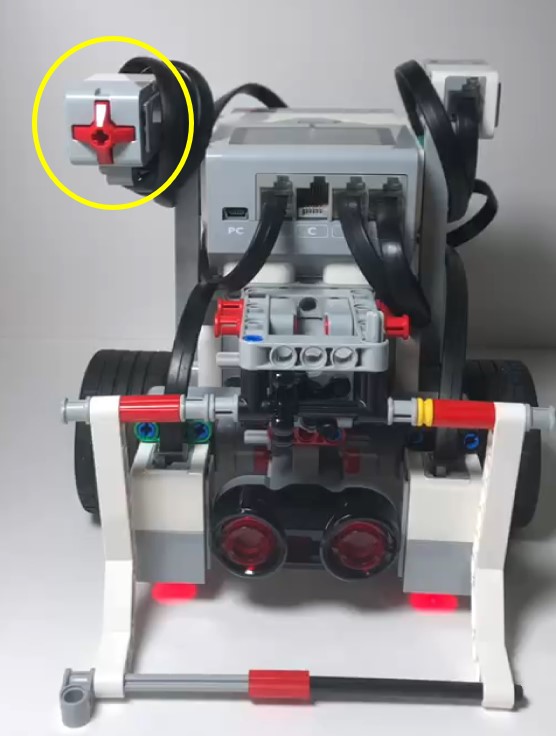
Another way to identify stalling is to use touch sensor. Firstly, mount the touch sensor at a point where it could be pressed down when stalling happens. In the below picture, a touch sensor is deployed at a position where the front attachment could press it down when reaching the upper most position.
In the following sample code, the medium motor will run till the touch sensor is pressed. It then stops, pauses 2 seconds and then reverses spinning.

Using touch sensor could identify collision and then catch certain scenarios of motor stalling, but it is not possible to catch all the conditions unless you install multiple touch sensors on your vehicle.
Method 3: Use Motor Rotation -> Degree
In this method, the program uses the Motor Rotation data to identify the motor degree change. It compares the data of rotation degree after a very short lapse of time. If the two sets of data is the same, stalling occurs.
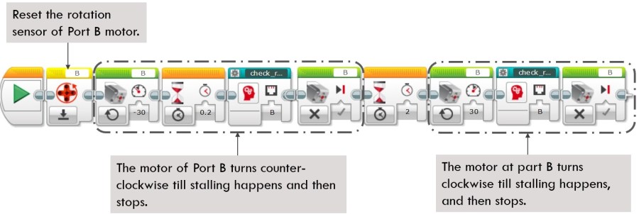
Still take the previous front attachment as an example. In the following code segment, the medium motor turns counter-clockwise till stalling happens. It stops, pauses 2 seconds, and then reserves spinning until stalling happens again. The stalling check function is wrapped in the block “check_motor_rotation” block. Let me show you how the block is defined.
Main code segment

Definition of “Check_motor_rotation” Block
This block contains an input parameter, which user could input with “A”, “B”, “C” or “D”, representing the port ID of the motor. Since the wired port input of Motor Rotation block requires value of 1 – 4 while users have gotten used to A-D as Port ID, it is necessary to use a switch block to convert the input value “A” – “D” into numbers 1 – 4.

Limitation of this method
Under some scenarios, the motor could still spin with the increased load. In the below front attachment design, it uses worm gear to increase the output torque by 24 times (1 worm gear and a 24-tooth gear). Therefore, even the two grip arms have touched and pressed with each other, the motor is not stalled fully. Using the above sample code, it continues spinning until destroying the whole front attachment structure.
In another example shown below, the code uses the previous “check_motor_rotation” block to identify whether the vehicle touches the wall, but it could not work as expected. When driving the vehicle to the wall, the big motors are spinning slower than before, but they are not stalled fully. This problem happens because the big motors could endure bigger torque. When the friction between the tiles and the ground is not big enough, the two wheels driven by big motors are skidding on the ground.

Method 4: Use Motor Rotation -> Current Power
In the previous method 3, we introduced the usage of motor’s rotation degree, but that method has its limitation. When the external torque is not big enough and the motor could still spin under the load, it could not recognize the stalling.
Please note that the output power or the speed of motor has decreased when load increases, although the motors are not fully stalled. Therefore, we could check power level to verify the stalling status.
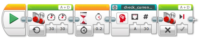
Still take the above example of vehicle driving to the wall. The code will use MoveTank block to drive the two wheels forward, until the current power of one of the motors (here using motor at Port A) falls below 20. It indicates that the wheels are skidding and motors are enduring increased load. The code then stops the motors.
Main code segment

Just one thing needs additional attention. When using the Current Power as a measurement, if the power level is positive (the motor is turning clockwise), the stalling threshold value should be smaller than the expected power level. On the contrary, if the power level is negative (the motor is turning anti-clockwise), the stalling threshold value should be bigger than the expected power level. The following sample code shows this point clearly.

Using this method to rewrite the above example of vehicle touching the wall. The main code segment keeps unchanged, and I revises the definition of “change_current_power” block, as shown below.
Main code segment:
“check_current_power” block
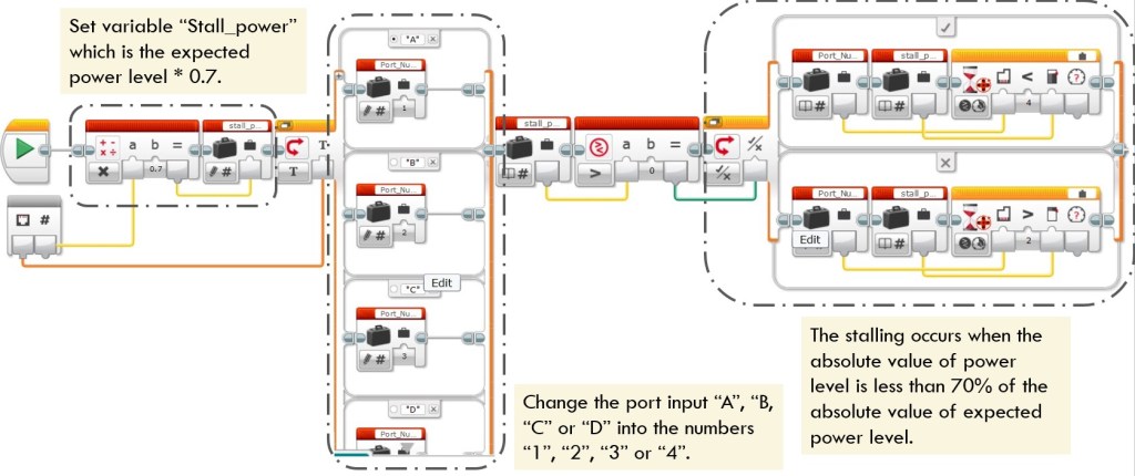
This block contains two input parameters. One is the port ID. Users could input letter “A”, “B”, “C” or “D” to represent the port the motor is connected to. However, the wired port input of Motor Rotation block could only accept number 1-4 as port ID. Therefore, the code uses a switch block to convert letter A-D into number 1-4.
The other input parameter is the expected power level. It is multiplied by 0.7 as the stalling threshold power and stores this value into variable “Stall_power”. The stalling occurs when the absolute value of power level is less than 70% that of expected power level. the threadhold “70%” could be adjusted by different scenarios.
Run the program and we notice that the vehicle identifies the stalling and stops at the wall.
Which method is better?
Method 3 and Method 4 are typical ways to handle motor stalling, especially when your model is a bit more autonomous or needs to do a series of relevant activities. Using either of the methods could enhance the robustness of your model.
However, if you could always ensure the initial position of your model or the overall operation is straight forward, estimating running time is a simple method. If the touch sensor could stably identify the stalling status, that is also a good choice.
That is all for this post. Feel clearer about how to identify and prevent stalling of your EV3 robot? Enjoy the coding and have fun!
Note: All the analysis articles are copyright products of http://www.thecodingfun.com. Anyone re-posting them should credit author and original source. Anyone using them for commercial purposes or translating them into other languages should notify TheCodingFun and get confirmation first. All Rights Reserved.

Pingback: LEGO MindStorms EV3 – Issues of Detecting Stalling in Micro Python 2.0 – The Coding Fun