
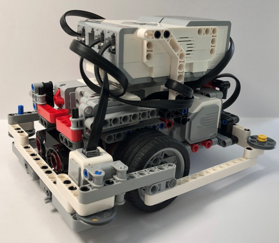
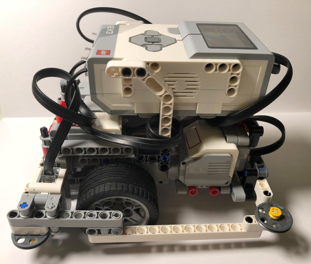
This time, I will explain another LEGO EV3 model – Droid Bot 2. This model is different from previous introduced ones. It has both external framework and guiding wheels at each corner. This feature is especially helpful when it needs to square up with a wall or runs alone a wall. Let me show a short video of how this model works.
Please note that this model’s specification comes from EV3 Lessons website. You could find its step-by-step specification at this address: http://ev3lessons.com/en/RobotDesigns.html
In this post, I will explain its mechanical structure. In the next post, I will introduce the sample code to run alone a wall.
Chassis Design
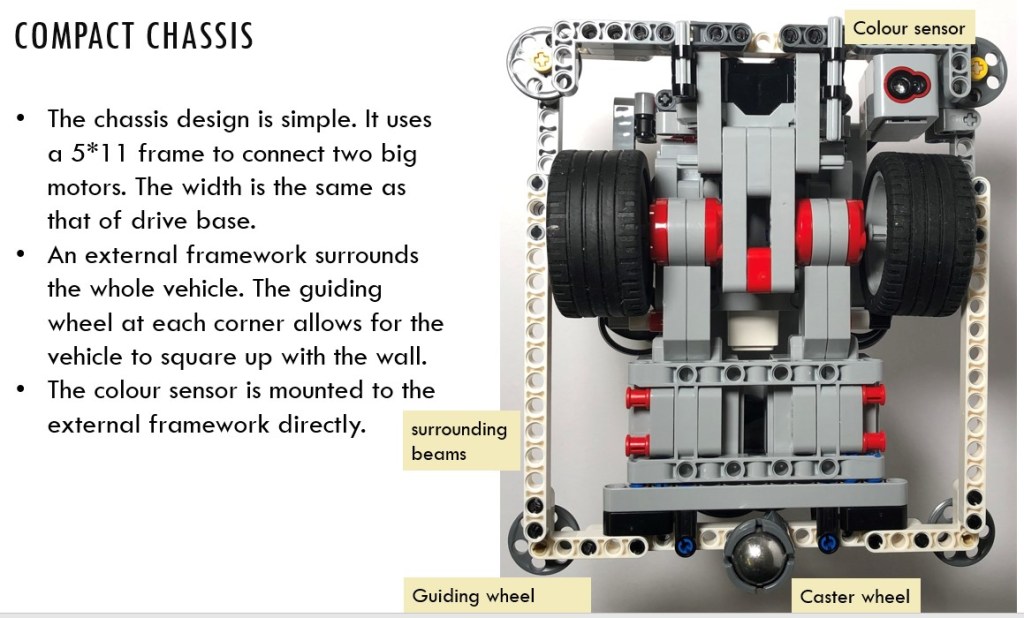
The chassis of the vehicle is simple. It uses a 5*11 frame to connect two big motors together. The distance between the two big motors is the same as that of the drive base, which is a sample model included in the LEGO MindStorms EV3 software.
An external framework surrounds the whole vehicle. Each side of the framework keeps flat so that the vehicle could align with the wall. The guiding wheel at corner allows for the vehicle to run alone the wall.
Caster Wheel
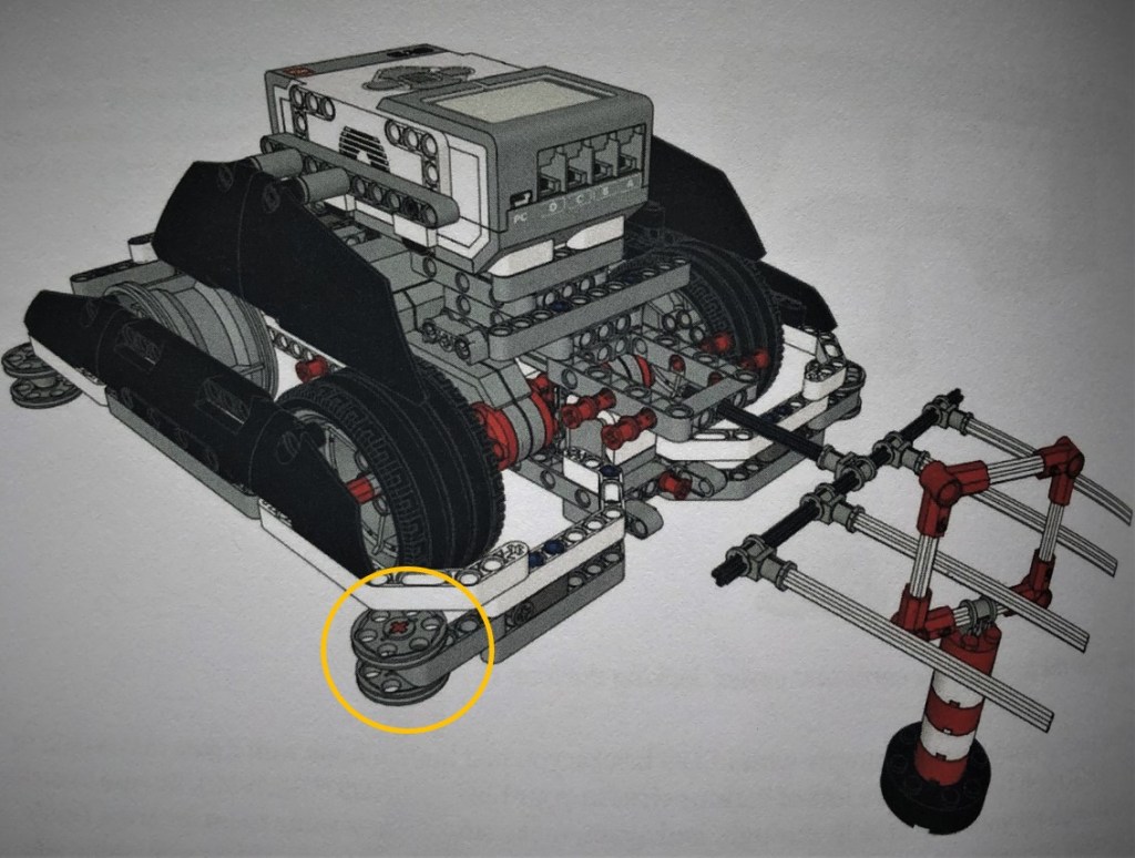
Like drive base model, this model is also a three-wheel vehicle. The caster wheel is attached to the external framework with a very simple structure – a black connector peg. The caster wheel could revolve inside the spin hole, but this spinning does not influence the motion of the vehicle.

External Framework
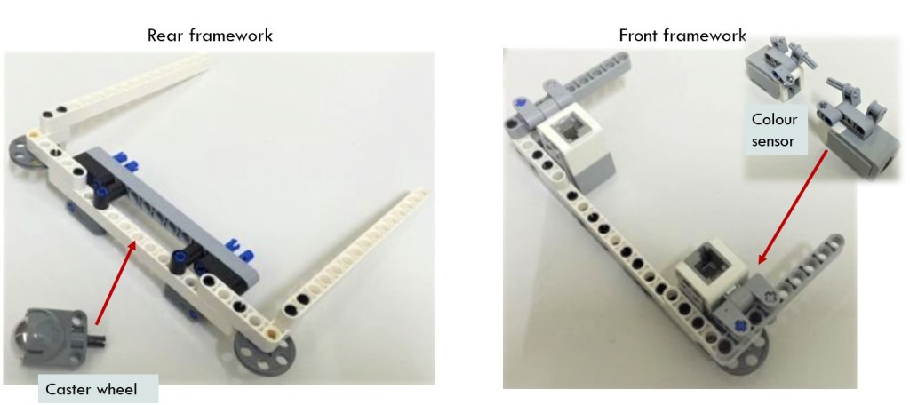
The whole vehicle is surrounded by the external framework, but there is no any beam long enough to cover the whole length of the vehicle. Therefore, the external framework consists of two parts – the front and rear parts. They are connected at the position of front wheels with a double-connector peg.
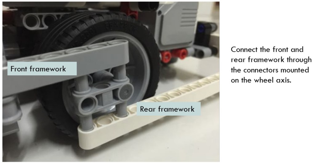
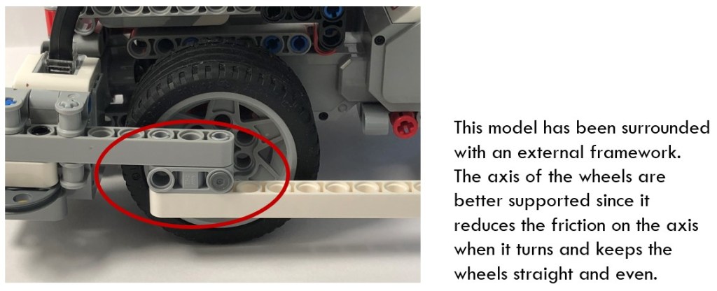
As I introduced in other model COR3 with external framework, the axles of the wheels are better supported since the framework reduces the friction on the axles and keeps the wheels straight and even.
Guiding Wheels
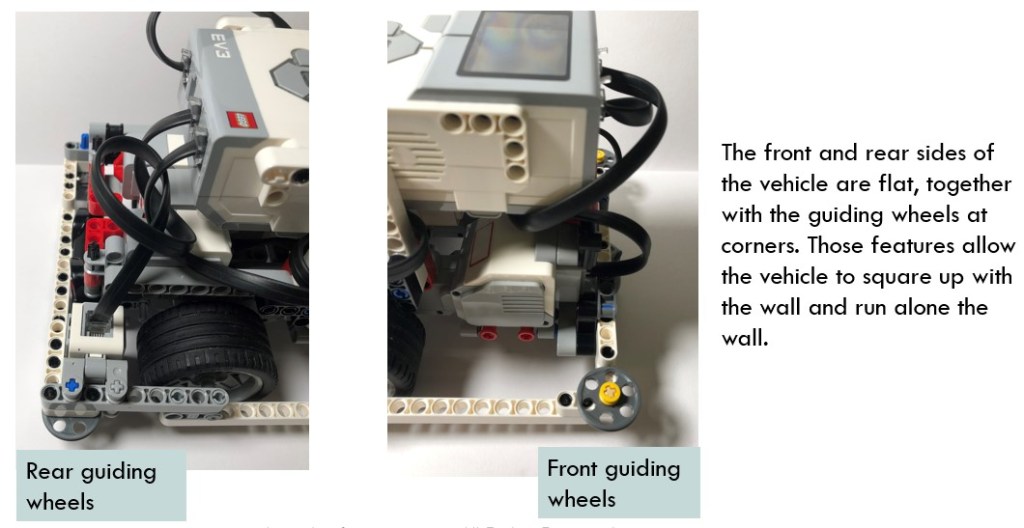
The guiding wheel allows for the vehicle to move alone the wall easier because the rolling friction between the wheels and wall could reduce the resistance.
Another Model with External Framework and Guiding Wheels
In the book “Winning Deisgn!”, the author James Jeffery Trobaugh also presented a similar model. I would say that such models with external framework and guiding wheels are very popular in FLL and WRO competitions since those matches require a vehicle to accomplish a series of missions, such as carrying objects from one place to another, running a long distance without any human interference, etc. It is a winning technique that your vehicle could square up with the wall or run alone with it.
Mount Medium Motor and Sensors
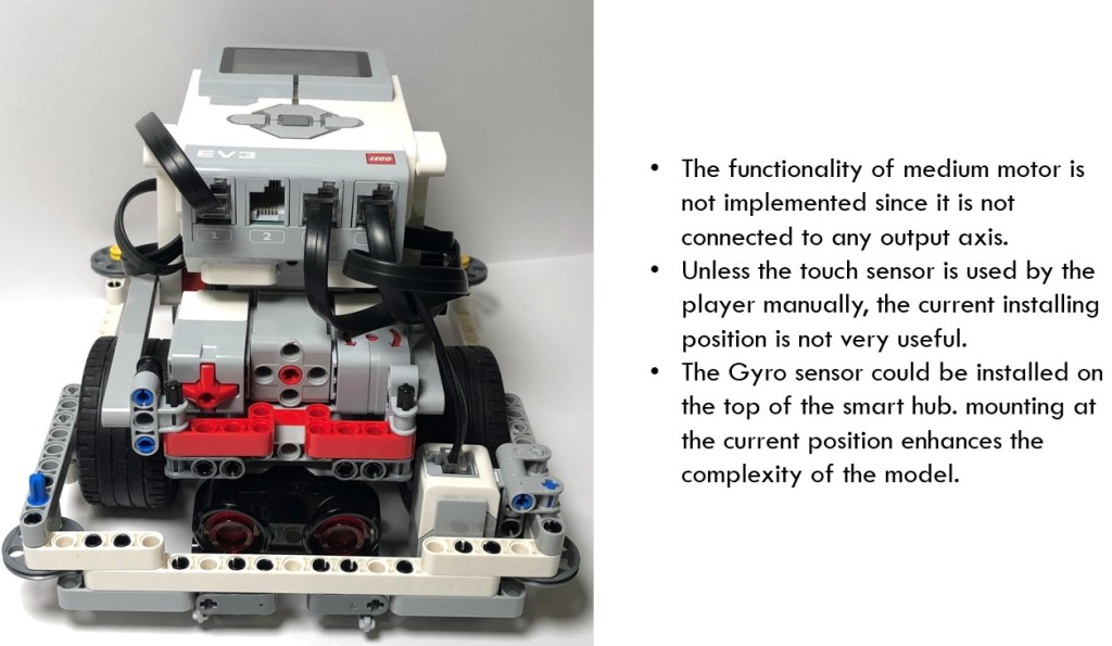
From the front view, we could see the position of medium motors, touch sensor and gyro sensor clearly. The functionality of medium motor is not implemented since it is not connected with any output axis.
I am curious why the touch sensor is put at the current position. If it is used to identify the collision, it should be installed at the edge of the vehicle or stretch out a bit.
In terms of gyro sensor, usually it is plugged to the side of the smart hub. It is not sensible to put gyro sensor beside the medium motor because in this way, it occupies the space where the medium motor connects axles and other output shafts.
The assembly of the vehicle is not so simple. In another model Discovery, both medium motor and sensors have compact connection structure and are able to plug into and pull off from the vehicle conveniently.
In the following sections, let me briefly introduce how the medium motor and sensors are mounted to the vehicle body.
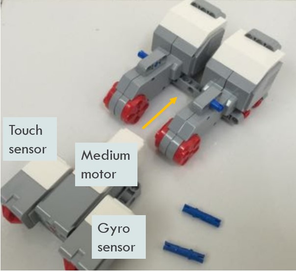
Mount the medium motor, touch sensor and gyro sensor
The medium motor, touch sensor and gyro sensor are assembled to the big motors. They are actually part of the vehicle body before any other fixing devices are added. Therefore, it is difficult to dismount them.
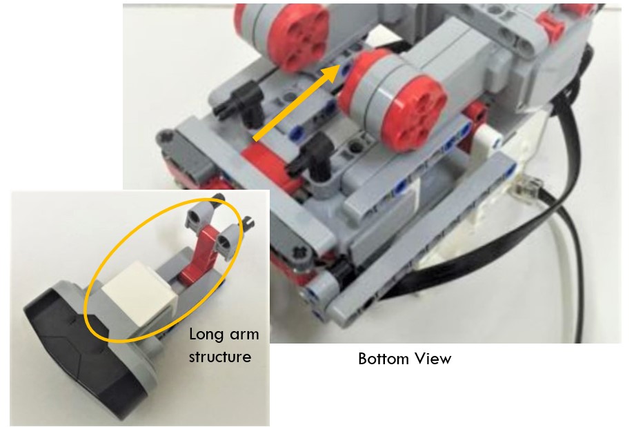
Assembly the ultrasonic sensor
The connection structure of ultrasonic sensor is also a bit complicated. It uses beams and multiple connectors to form a long arm, and then inserts that long arm into the gap between two big motors. It is also difficult to dismount it.
Features of the Model
That is the overall structure of this model. I will summarize its advantages and disadvantages here:

As you can see, there are no perfect models. In the next post, I will present sample code to make it square up and run alone the wall. Stay tuned!
Note: All the analysis articles are copyright products of http://www.thecodingfun.com. Anyone re-posting them should credit author and original source. Anyone using them for commercial purposes or translating them into other languages should notify TheCodingFun and get confirmation first. All Rights Reserved.

How much of an unique article, keep on posting better half
LikeLike
Muchos Gracias for your article post.Much thanks again. Much obliged.
LikeLike