
No matter you participate in FLL (First Lego League) or WRO (World Robot Olympiad) competition, or just play your LEGO vehicle for practice or fun, one basic functionality of your vehicle is to run alone a line.
In both FLL and WRO, the routes on the match field are depicted in black. Therefore, the vehicle should be able to identify the black line and then follow it, that is what we call the “Line Follower”.
Follow the Edge of Line
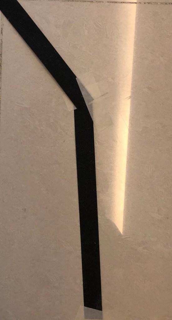
The black line represents the route and it is not just a thin line, but a line with a width of 3-4 inches. When a vehicle follows the line, it actually is following the edge of the line. Because if it follows the line directly, when it drifts off the line and the sensor sees the white area, it does not know which side of the line it is on, therefore, could not return to the black line again.
So the first step, you need to decide which edge of the route the vehicle is planning to follow. The code to follow left edge or right edge of the line is similar, but the judgement condition is the opposite.

Typical ways to follow line
There are different methods to follow a line, from simplest versions to more complicated ones. In the following sections, I will show you how to realize those functionalities by using the newly released LEGO MicroPython 2.0.

Calibration of Light Sensor
Before implementing the line following code, the first thing is to calibrate the light sensor. Its purpose is to log the white color and black color’s reflection values because the same color will show reflection value differently when the light intensity of ambient environment is different.
Some code developer would like to record those calibration data in a file and later on, just extract the data from the file conveniently. Here I am doing the demonstration, so just record the calibration value into the Output area by using Print() method. In my case, I got value 3 for black route surface, and 62 for non-route surface. I will use the data in the following line following functions.

2-Level Line Follower
This is the simplest version of line follower. In the following example, the vehicle will follow the left edge of the black route. When sensor’s light reflection value <= threshold value, right motor will run and left motor will stop. The effect will be that the vehicle turns left. Please pay attention that there is one line of code “wait(10)”, meaning that for each loop, there is a 10 millisecond interval of waiting. You could adjust this value freely. The bigger this value is, the less accurate the control will be and the more wiggly the vehicle will move forward.
However, if you reduces the waiting time too much or completely removes this line of code, the adjustment is too frequent and your vehicle might kind of like vibrate or shake too much.

3-Level Line Follower
This line following method is actually an upgraded version of 2-Level Line Follower. When sensor’s light reflection value <= threadhold_1, right motor runs and left motor stops; when light reflection value >= threshold_2, left motor runs and right motor stops. If the value falls within the middle, both left and right motors will run at the same speed, meaning that the vehicle moves forward straight. Please pay attention that in this example, I use motor.run_angle() method, so each adjustment will make the corresponding motor run an angle of 50 degrees. You could adjust this angle or use motor.run() to implement the same functionality.
Besides 3-staged line follower, more stages could be defined to control more accurately, but we have to make compromise between easiness and accuracy.

PID Line Follower
Now I will briefly explain what is PID controller. P represents Proportional. The adjustment is proportional to the error (the difference between light sensor’s value and target value). I represents Integral, which calculates the historically accumulated error. D represents Derivative, which forecasts the future error based on the past error. Combine the three parts and assign factors Kp, Ki and Kd to each of them and we can get a value of Turn, which will be added/subtracted from the existing motor speed to realize PID controlling, as shown below.

Please note that Power A (the left motor) is always plus Turn, and Power B (the right motor) is always minus Turn. It does not mean that Power A would always be bigger than Power B since Turn’s value could be either positive or negative.
The basic PID controller should work for many different control problems, and can be customized to use only as a P or PI controller instead of a PID.
In the following sections, I will introduce the code of P controller and PID controller respectively.
Proportional Line Follower
In this P controller example, only Proportional part is considered and then apply to the adjustment of motors.

PID Line Follower
In a typical PID controller, please note that at the end of each loop, error variable value should be assigned to last_error variable, so that in the next loop iteration, integral could accumulate the historical error values by adding error to last_error value.
There are many parameters which could be customized in PID, such as Black, White, threshold, Drive_SPEED and P, I and D factors. In the next section, I will explain how to use log file to analyze the line following result and make adjustment to PID factors.

Try and Trial to Tune Parameters
The best P or PID controller will be different for each kind of line (line width, sharpness of curves etc.), so we should tune the P controller or PID controller for a particular kind of line and robot. In a word, the PID algorithm will work for many robots (and many tasks) but the parameters, Kp, Ki and Kd and threshold have to be tuned for each robot and each application.
(Source: “PID Controller for LEGO Mindstorms Robots” by J. Sluka)
Different PID Parameter Combination on the Effect of Vehicle:
This PID controller use Kp = 1.2, Ki = 0.005 and Kd = 0.01. It runs smoothly on straight line, but could not adjust well after turning.

This PID parameters uses Kp = 4.2, Ki = 0.008, Kd = 0.01. It wiggles a bit on the straight line due to the big value of Kp, but adjusts itself well at the turning point.

Summary
PID looks like an advanced topic, but you do not need to get scared by its technical name. Try to refer to the above code to create your own PID line following code and it is not so complicated actually.
There is an excellent document which explains PID technique from the scratch, which is written by J. Sluka. If you have time, it deserves a concentrated reading. The address is here: http://www.inpharmix.com/jps/PID_Controller_For_Lego_Mindstorms_Robots.html
And finally, don’t forget to enjoy the coding and have fun!
Note: All the analysis articles are copyright products of http://www.thecodingfun.com. Anyone re-posting them should credit author and original source. Anyone using them for commercial purposes or translating them into other languages should notify TheCodingFun and get confirmation first. All Rights Reserved.

Hallo Usually I do not learn article on blogs, however I wish to say that this write-up very pressured me to try and do it! Your writing taste has been amazed me. Thanks, very great post. danke
LikeLike
Pingback: LEGO MindStorms EV3 – Align with a Line – The Coding Fun
These are the best with tea or coffee
LikeLike