

On YouTube, I just accidentally found a video introducing a self-balanced robot controlled with PID. That is really amazing. However, when I tried to build the model and copied its code, I met some problems. It seems not as easy to get the robot keeping balanced as shown in the video.
In this post, I would like to explain a bit more about the self-balanced model based on the introduction of the video. Hopefully, it could help you understand it better and create such a model successfully.
The original video below contains both model instruction and PID explanation, so I will not introduce them again in this post.
The Program
The following program is a complete copy of the initial one. I pasted here just to show it clearly. Yes, the whole program is pretty short. The only thing it is doing is to control the motor’s rotation direction and power level via the PID method.

Target Value of PID
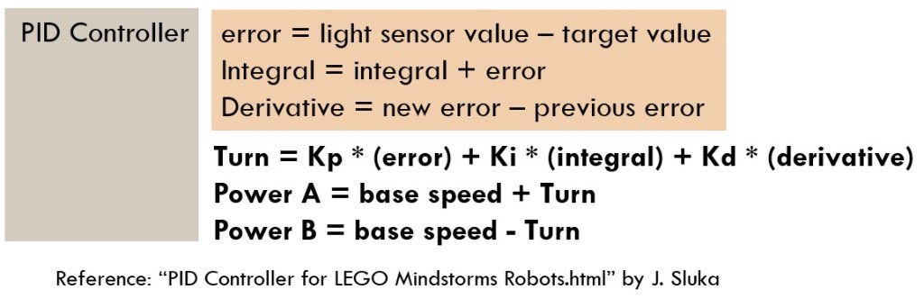
If you have designed a robot vehicle to follow a line, you might not feel strange about PID control. When following the line, the robot vehicle compares the reflective light of the Color Sensor with the target value, and gets error, integral and derivative values. It calculates how much power should apply to left motor and right motor respectively.
For self-balancing robot, the first step of PID control is not to check reflective light value of Color Sensor, but to check the the roll angle. The built-in gyro sensor could measure smart hub’s orientation. When the smart hub is put in the way shown in the model, its roll angle is around 90 degrees. When the model is losing balance and falling down, the roll angle deviates from the balanced position of 90 degrees. The farther the angle deviates, the more possible the robot falls. Therefore, The input of PID control for this model is roll angle.
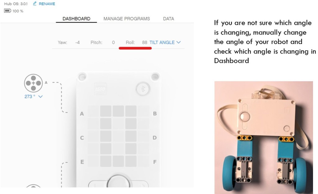
Please note that if the smart hub on your model is facing different direction, the measured angle might be different. In the demo model, the smart hub is put along the left side and the target roll angle is 90 degrees. However, if you put smart hub along the right side, as shown below, the target roll angle will be -90 degrees.

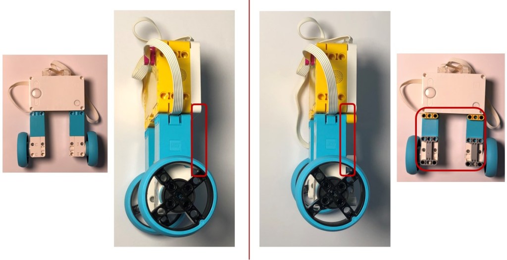
Why does the program set the the target angle to 89.95 instead of 90 degrees? It is related to the model’s geometric structure. As shown below, the model is not completely symmetric because the width of the motor is a bit smaller than that of the smart hub. The gravity center of the model falls aside when roll angle is 90 degrees. The robot is balanced when it tilts a bit and the roll angle is around 89.95 degrees.
In order to keep the robot more balanced front and back side, I add more blocks on the front side, so that the target angle could be closer to 90 degrees. Without those supplementary blocks (yellow and gray blocks), the robot is prone to move backward and lose balance.

Motor Rotation Direction
Another area causing confusion is which motor is regarded as left motor, and which motor is taken as right motor. Actually, there is not absolute answer. As shown in the below diagram. when the robot is going to fall to the right, both wheels should turn clockwise, so as to restore it to the upright position. Therefore, no matter which wheels you set as left or right wheels, just ensure that the wheels turning direction is consistent with the falling direction.
The final effect might be just like this:
- “set movement motors to E+A”, you need to use: “start moving straight at (result * power) %power”.
- “set movement motors to A+E”, you need to use: “start moving straight at -(result*power) %power”.

Use “start moving at %power” Code Segment
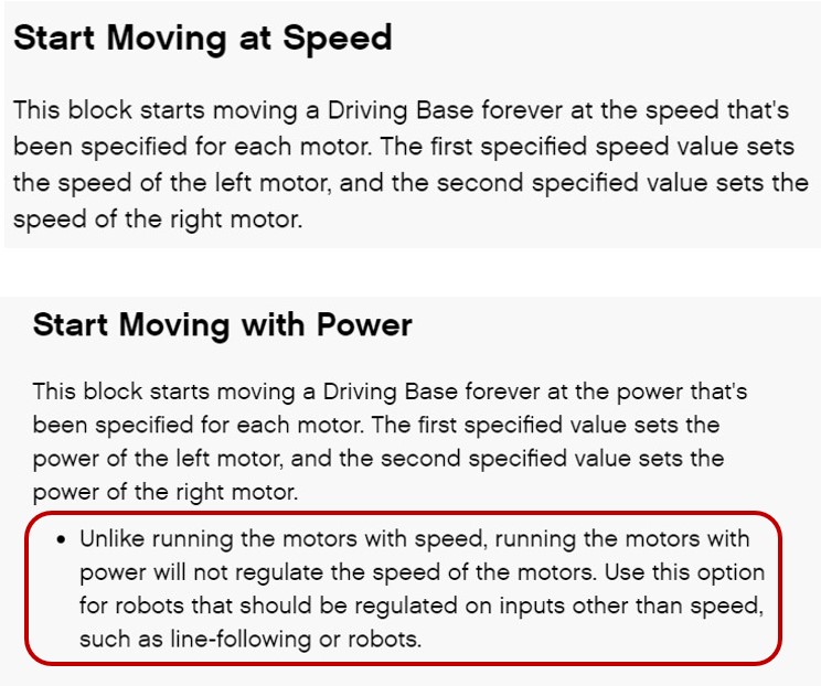
Another point is to ensure using “start moving at … %power” on the last line of the PID control code. As mentioned in the Help Document, “start moving at %power” block is used when the program needs to regulate the input of robot, such as line-following robots. If you use blocks “start moving at speed”, you might not be able to realize PID control.
This section explains the PID control program and some key parameters or programming blocks. In the next section, I will introduce physical factors which influence the final effect of the robot.
Factors to Influence the Balance
Wheel Size
One factor to influence the balance is the wheel size. The wheel size in core set is 5.6cm in diameter. The wheel size in expansion set is 8.8cm in diameter. If you change small wheels to big ones, with the same motor power, the distance of the wheels traveling per rotation is different. We need to adjust parameters to accommodate this difference.
A reference for the two conditions:
- Small wheels -> set “power” parameter to 1.9
- Big wheels -> set “power” parameter to 1.5

Symmetric Structure
Keep the model as symmetric as possible. It will help to keep the gravity center closer to the center line, so the robot could keep balanced in an upright position.
Running Surface
If the surface is smooth, it is difficult for this robot to maintain balance. As the smooth surface has less friction, it is difficult to control the rotation degrees of the wheels, therefore, the robot is easy to lose balance. The demo model in this project could balance successfully on the mattress, but fails on the tile floor.

Final Version
The following video clips shows the controlling effect with small wheels and big wheels, respectively. It really works even when I tap it with figures! Neither model nor code is complicated, so come to give it a try!
Note: All the analysis articles are copyright products of http://www.thecodingfun.com. Anyone re-posting them should credit author and original source. Anyone using them for commercial purposes or translating them into other languages should notify TheCodingFun and get confirmation first. All Rights Reserved.
